When you visit any website, it may store or retrieve information on your browser, mostly in the form of cookies. This information might be about you, your preferences or your device and is mostly used to make the site work as you expect it to. The information does not usually directly identify you, but it can give you a more personalized web experience.
Because we respect your right to privacy, you can choose not to allow some types of cookies. However, blocking some types of cookies may impact your experience of the site and the services we are able to offer.
You Allow:
Strictly Necessary Cookies(Required)
These cookies are necessary for you to browse our website and use its fundamental services,and they don't require your consent.These cookies allow us to offer you the essential functions of the website(account access,language used,order played,payment etc),and can also be used for identity verification and security.If you disable them,we will not able to fulfill your basic request.
These cookies collect anonymous information on your online operation behaviors that help us improve website construction. If you reject these cookies, you may not be able to use certain features of our websites and services.
These cookies allow us to remember the choices you have made about your preferences, such as what language you prefer. If you reject these cookies, you may feel that the efficiency of browsing the web has decreased.
These cookies carry out personalized activities to advertise products and services which you are interested. If you reject these cookies, you will still see advertisements that are not much relevant to your interest or demand.


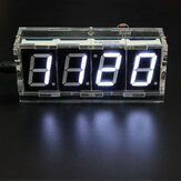


fhiew Solder in this order: resistors, crystal oscillator, 4-pin header, capacitors, IC sockets, battery holder, power socket, switches, buzzer, transistors, LDR, thermistor. The 4-pin header mounts near the top left of the PCB. Bend the pins upwards 20° to fit hole in the case. LDR (GM): (above the battery, height .5cm above the board) The thermistor (RM) middle on the top edge, height 9mm above the board. Check everything before adding the LED displays. Solder Digits 3 & 4 upside down. Check fit of the displays: I had to file some of the feet slightly. Attach adhesive diffuser. Insert ICs & battery Case: do the rear first. Setting: Lower button: parameter select. Top button: Show date or increase by 1. The parameters: Min; Hour; Alarm min; Alarm h; Alarm on-off (0000 or 1111); Month; Date; Day of week; Auto brightness on-off (0 _ _ 0 or 1 _ _ 1 shown); Hourly chime on-off (_ 0 0 _ or _ 1 1 _ shown)
2021-09-27 10:39:13 Helpful (0)